Generation
BoSS Ladderspan Something, something guide
Introduction
Please read this Userguide carefully. Please note that diagrams are for illustrative purposes only. User guides are also available - please contact us for more information.
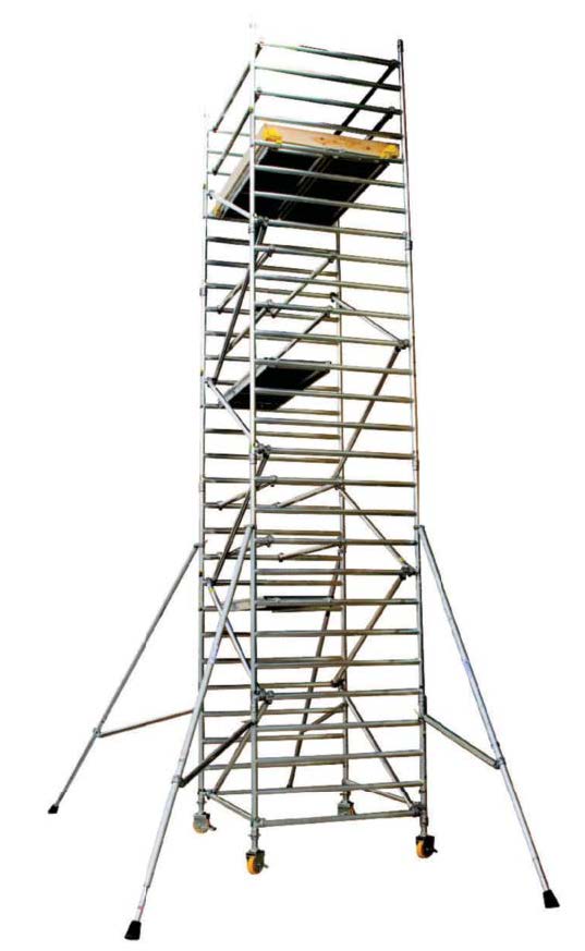
BoSS mobile aluminium towers are light-weight scaffold towers used throughout the building and construction industry for both indoor and outdoor access solutions, where a stable and secure platform is required. Ideal for maintenance and installation work or short-term access, the highly versatile towers provide a strong working platform for a variety of heights.
This User Guide provides you with step by step instructions to ensure your system is assembled easily and safely using the 3T (Through The Trapdoor) method.
The law requires that personnel erecting, dismantling or altering towers must be competent. Any person erecting a BoSS mobile tower must have a copy of this guide. For further information on the use of mobile access and working towers, consult the PASMA operators‘ code of practice.
If you need further information, design advice, additional guides or any other help with this product, please contact your local Altrad Generation Hire & Sale Branch.
Compliances
The BoSS Clima aluminium system has been tested and certified to EN 1004: 2004 Class 3

Preparation and Inspection
Inspect the equipment before use to ensure that it is not damaged and that it functions properly. Damaged or incorrect components should not be used.
Safe Use
- Check that all components are on site, undamaged and that they are functioning correctly - (refer to Checklist and Quantity Schedules). Damaged or incorrect components should not be used.)
- Check if the ground on which the mobile access tower is to be erected and moved is capable of supporting the tower.
- The safe working load is 275 kgs (606lbs) per platform level, uniformly distributed up to a maximum of 950kgs (2100lbs), per tower (including self weight).
- Towers must always be climbed from the inside using the built-in ladder during assembly and use.
- It is recommended that towers should be tied to a solid structure when left unattended.
- Adjustable legs should only be used for levelling.
Lifting of Equipment
- Tower components should be lifted using a reliable lifting material (e.g. strong rope), employing a reliable knot (e.g. clove hitch), to ensure safe fastening and always lift within the footprint of the tower.
- Assembled mobile towers
Stabilisers/Ballast
- Stabilisers or outriggers and ballast weights should always be fitted when specified.
- The Quantity Schedules show the recommended stabilisation. In circumstances where there is restricted ground clearance for stabilisers/outriggers, contact your supplier for advice. Ballast must be made up of solid materials (i.e. not water or loose sand) and should not be positioned to overload individual legs. Ballast should be secured against accidental removal where practicable, and be supported on the lowest rung of the bottom frame.
Movement
- The tower should only be moved by manual effort, and only from the base.
- Beware of live electrical apparatus when moving the tower (particularly overhead), plus wires or moving parts of machinery.
- No person or materials should be on the tower during movement.
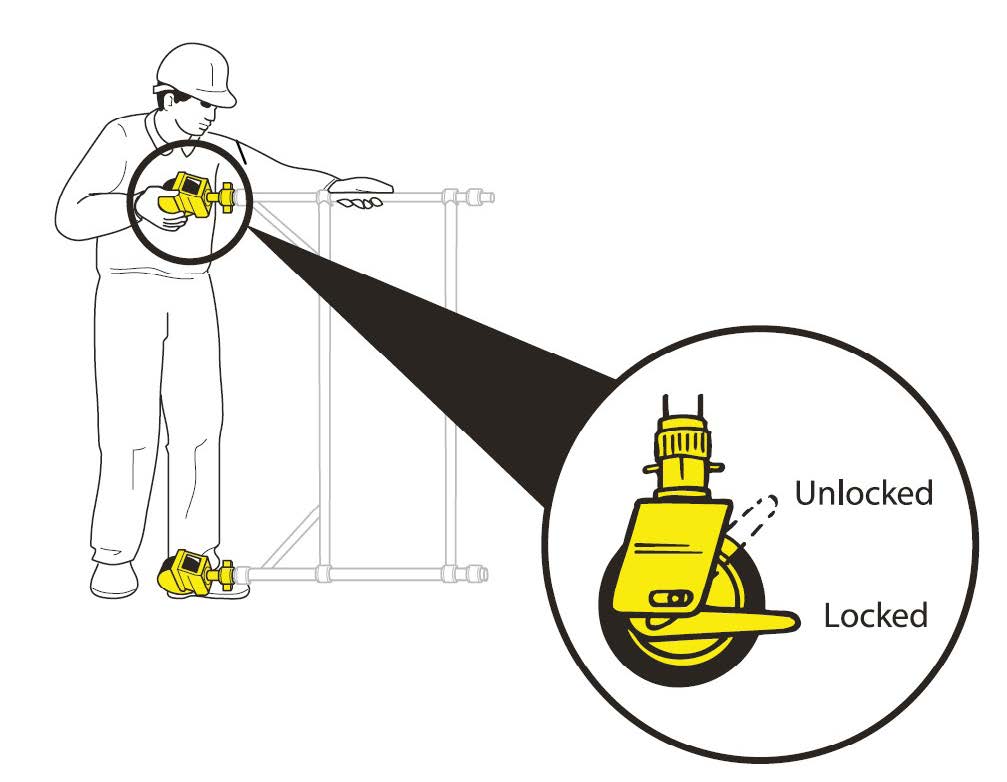
- Caution should be exercised when wheeling a tower over rough, uneven or sloping ground, taking care to unlock and lock castors. If stabilisers are fitted, they should only be lifted maximum of 25mm above the ground to clear ground obstructions.
- The overall height of the tower when being moved should not exceed 2.5 times the minimum base dimensions, or 4 metres overall height.
- Before use, check that the tower is still correct and complete.
- After every movement of the tower, use a spirit level to check that it is vertical and level and set the adjustable legs as required.
- Do not move the tower in wind speeds over 7.7 metres per second (17mph).
During Use
- Beware of high winds in exposed, gusty or medium breeze conditions. We recommend that in wind speeds over 7.7 metres per second (17 mph), cease working on the tower and do not attempt to move it. If the wind becomes a strong breeze (expected to reach 11.3 metres per second - 25 mph) tie the tower to a rigid structure. If the wind is likely to reach gale force (over 18 metres per second - 40 mph), the tower should be dismantled.
- Beware of open ended buildings, which can cause a funnelling effect.
- Do not abuse equipment. Damaged or incorrect components should not be used.
- Raising and lowering components, tools, and/or materials by rope should be conducted within the lower base. Ensure that the safe working load of the supporting decks and the tower structure is not exceeded.
- The assembled tower is a working platform and should not be used as a means of access or egress to other structures.
- Beware of horizontal forces (e.g. power tools) which could generate instability. Maximum horizontal force 20kg.
- Mobile towers are not designed to be suspended - please refer to your supplier for advice.
- Do not use boxes or stepladders or other objects on the platform to gain extra height.
Ties
- Ties should be used when the tower goes beyond its safe height, beyond the limits of the stabilisers/outriggers or if there is a danger of instability. They should be rigid, two way ties fastened to both uprights of the frame with load-bearing right angled or swivel couplers. Only couplers suitable for the 50.8mm diameter tube of the tower should be used. Ideally, ties should be secured to both faces of a solid structure by means of anchorages.
- The tie frequency may vary depending on the application, but they should (at a minimum) be every 4 metres in height.
- For further information on tying-in a tower please contact your supplier or BoSS.
Maintenance - Storage - Transport
- All components and their parts should be regularly inspected to identify damage; particularly to joints. Lost or broken parts should be replaced, and any tubing with indentation greater than 5mm should not be used and put to one side for manufacture repair. Adjustable leg threads should be cleaned and lightly lubricated to keep them free running.
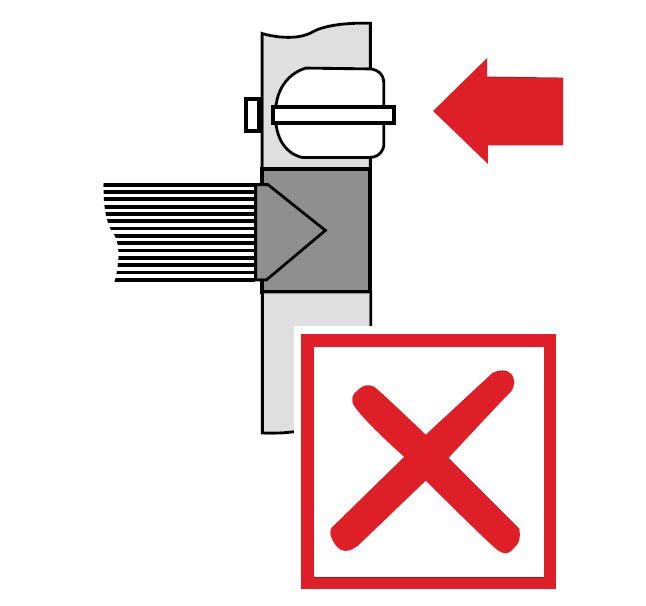
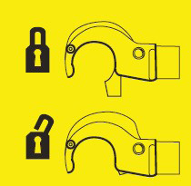
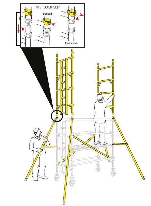
- Brace claws, frame interlock clips, trapdoor latches and platform windlocks should be regularly checked to ensure they lock correctly.
- Refer to the BoSS Userguide for detailed inspection and maintenance advice.
- Components should be stored with due care to prevent damage.
- Ensure components are not damaged by excessive strapping forces when transported.
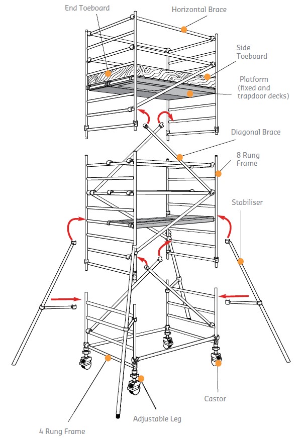
Diagram
1450 Width Towers - Quantity Schedule
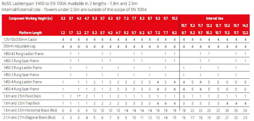
IMPORTANT: Please ensure you also read the Quantity Schedule
If you are unable to position the working platform easily from the ground, you may height. require an additional fixed platform for this tower weight
Number Of Working Load Platforms Allowed
The MAXIMUM SAFE WORKING LOAD (the combined weight of the users, tools and materials) that may be placed on the tower is the total weight less than the self weight of the tower. The total weight for the towers shown in the schedule is 950kg.
Example 1: A 1450 tower built using the 3T method with a 4.2m platform height and a platform length of 1.8m has a self weight of 180kg. 950kg - 180kg = 770kg maximum safe working load total weight self weight (users, tools and materials)
Example 2: A 1450 tower built using the 3T method with a 11.7m platform height and a platform length of 2.5m has a self weight of 449kg. 950kg - 449kg = 501kg maximum safe working load total weight self weight (users, tools and materials) For greater heights and loads, consult BoSS for guidance.
Platform Loading
On a 1450 tower, a platform may comprise of a single deck or two decks placed side by side. The maximum safe working load (the combined weight of the users, tools and materials) that may be placed on a platform is 275kg. This must be evenly distributed over either one deck, or two decks placed side by side.
The quantities will enable BoSS towers to be built safely and therefore comply with the requirements of the Work at Height Regulations. They include double guardrails to all platforms. Toeboards will need to be added if any levels are used as working platforms and for storage of materials.
EN 1004 requires platforms at least every 4.2m, and these measures will exceed that requirement.
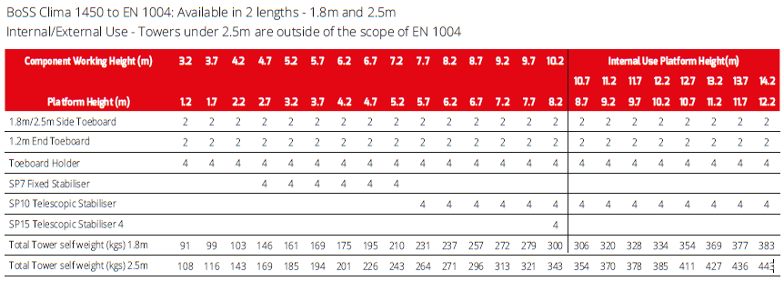
Ballast : Internal
There is no requirement for ballast on 1450 towers if using stabilisers as detailed in the table in the quantity schedule.
Mobile Outriggers
MP16 outriggers can be used instead of SP15 stabilisers, as detailed below. Mobile outrigger kits comprise of:
Stabilisers
To improve rigidity, larger stabilisers can be used at a lower level than shown in the 1450 Width Towers Quantity Schedule.
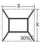
Angle of Stabiliser 1450 Tower
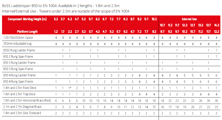
850 Width Towers - Quantity Schedule
IMPORTANT: Please ensure you also read the 1450 Width Tower Quantity Schedule.
- If you are unable to position the working platform easily from the ground, you may require an additional fixed platform for this tower height.
Number Of Working Load Platforms Allowed
The MAXIMUM SAFE WORKING LOAD (the combined weight of the users, tools and materials) that may be placed on the tower is the total weight less the self weight of the tower. The total weight for the towers shown in the schedule is 950kg.
Example 1: An 850 tower built using the 3T method with a 4.2m platform height and a platform length of 1.8m has a self weight of 151kg. 950kg - 151kg = 799kg maximum safe working load total weight self weight (users, tools and materials)
Example 2: An 850 tower built using the 3T method with a 11.7m platform height and a platform length of 2.5m has a self weight of 408kg. 950kg - 408kg = 542kg maximum safe working load total weight self weight (users, tools and materials) For greater heights and loads, consult Youngman for guidance.
Platform Loading
On an 850, tower a platform comprises of a single deck only. The maximum safe working load (the combined weight of the users, tools and materials) that may be placed on a platform is 275kg, evenly distributed over the deck.
The quantities on pages 13 and 14, will enable BoSS towers to be built safely and therefore comply with the requirements of the Work at Height Regulations 2005. They include double guardrails to all platforms, and toeboards will need to be added if any levels are used as working platforms and for storage of materials. EN 1004 requires platforms at least every 4.2m, and these measures will exceed that requirement.
Ballast: Internal
There is no requirement for ballast on 850 towers if using stabilisers as detailed in the table on Quantity Schedule.
Mobile Outriggers
MP16 outriggers can be used instead of SP15 stabilisers, as detailed below. Mobile outrigger kits comprise of:
Stabilisers
To improve rigidity, larger stabilisers can be used at a lower level than shown in 850 Quantity Schedule.
Angle of Stabiliser 850 Tower
Angle of Stabiliser 850 Tower
Assembly Procedure
Assembly and Dismantling Procedures When building a BoSS Tower:
- To comply with the Work at Height Regulations we show assembly procedures with platforms every 2 metres in height, and, the locating of guardrails in advance of climbing onto a platform to reduce the risk of a fall.
- All platforms feature double guardrails on both faces of either individual platforms or fully decked levels
- All guardrails should be 2 and 4 rungs (0.5m and 1.0m) above platforms.
- Never stand on an unguarded platform positioned above the first rung of a tower. If your risk assessment shows it necessary, you may also need to guardrail platforms at this level.
-
Always start building with the smallest height frames at the base of the tower:
Where all 3 frame heights are used in a tower, start with 2 rung frames at the base, with the 3 rung frames next and the 4 rung frames on the top. Refer to the quantity schedules for detail.
To Dismantle a BoSS Ladderspan Tower
- Remove toeboards, and pass down the tower.
- Unclip farthest end of braces and immediately go to protected trapdoor position on ladder to complete removal.
- Remove upper platforms from protected platform levels below.
- Pass removed components out of the tower to a colleague.
Safety Checklist
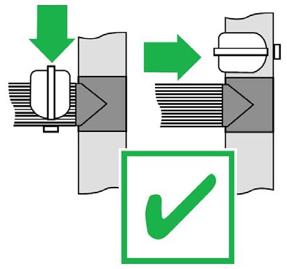
- Ensure all brace claws operate and lock correctly prior to erection.
- Inspect components prior to erection.
- Inspect tower prior to use.
- Tower upright and level.
- Castors locked and legs correctly adjusted.
- Diagonal braces fitted.
- Stabilisers/outriggers fitted as specified.
- Platforms located and windlocks on.
- Toeboards located.
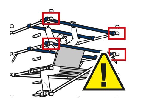
- Check guardrails are fitted correctly. See illustration below.
 |
 |
 |
 |
Assembly for 1450 Towers - 3T Method
Always start building with the smallest height frames at the base of the tower:
Where all 3 frame heights are used in a tower, start with 2 rung frames at the base, with the 3 rung frames next and the 4 rung frames on the top. Refer to the Quantity Schedules for detail. The procedure illustrated shows 4.2m platform height tower starting with a 2 rung frame. BoSS recommend two persons are used to build BoSS Towers. Above 4m height, it is essential that at least two persons are used. Only climb the tower from the inside.
1:
Push castor into adjustable leg. Push castor / adjustable leg assemblies into 2 rung span frame. Lock castors. Repeat procedure with 2 rung ladder frame. It is recommended that for ease of levelling a gap of 50mm is left between the bottom of the leg and the adjustable nut. Adjustable Legs are for levelling only. You must not adjust all four to gain extra height. Note: Base Plates can be fitted to adjustable legs in lieu of castors if it is not necessary to move the tower.
2:
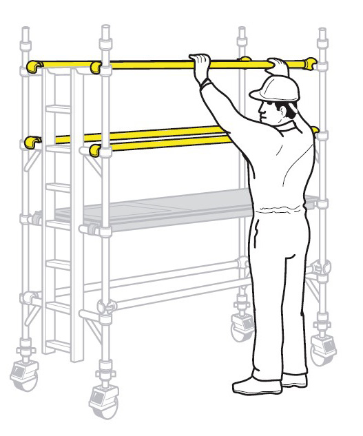
Fit one horizontal brace (red) onto the vertical of a span frame, just above the bottom rung, with the claw facing outwards. The frame will now be self supporting. Note: All locking claws must be opening before fitting.
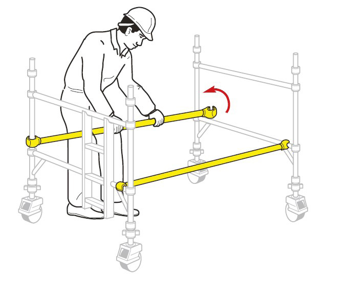
3:
Position the second end frame as shown and fit the other end of the horizontal brace onto the vertical, just above the bottom rung. Fit a second horizontal brace between the bottom rungs on the other side of the frames to square the tower.
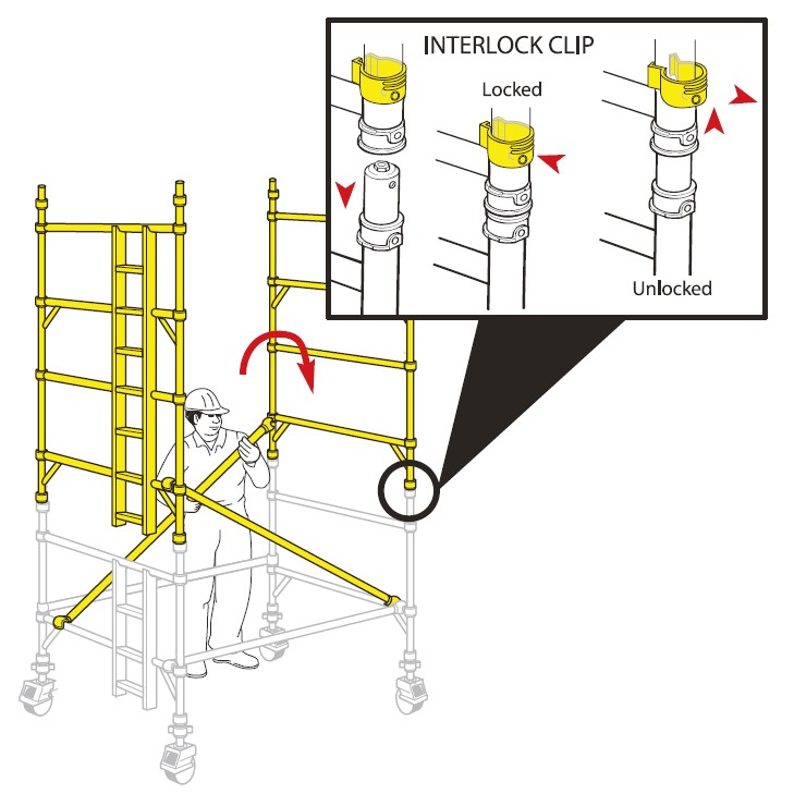
4:
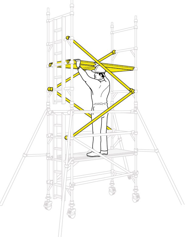
Fit 2 additional end frames, ensuring the frame interlock clips are engaged. Fit 2 diagonal braces (blue) in opposing directions between the 1st and 2nd rungs. Ensure the frames are vertical and level by checking with a spirit level and setting the adjustable legs as required. IMPORTANT - Only use the adjustable legs to level the tower and not to gain extra height.
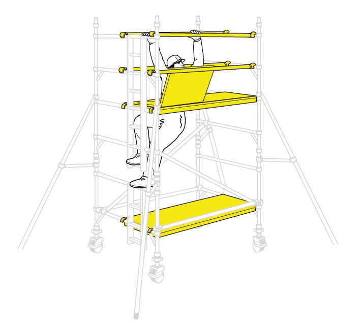
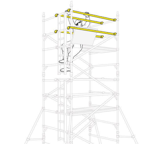
5:
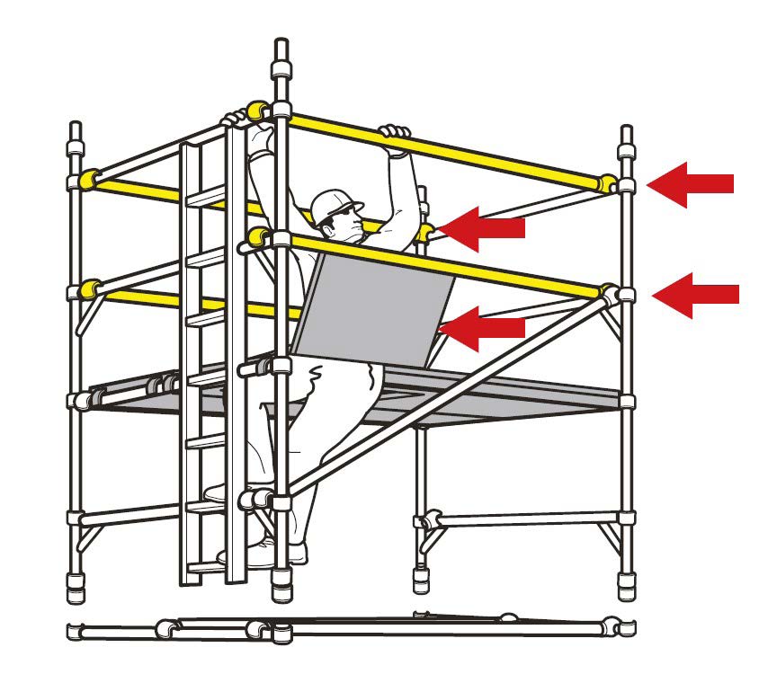
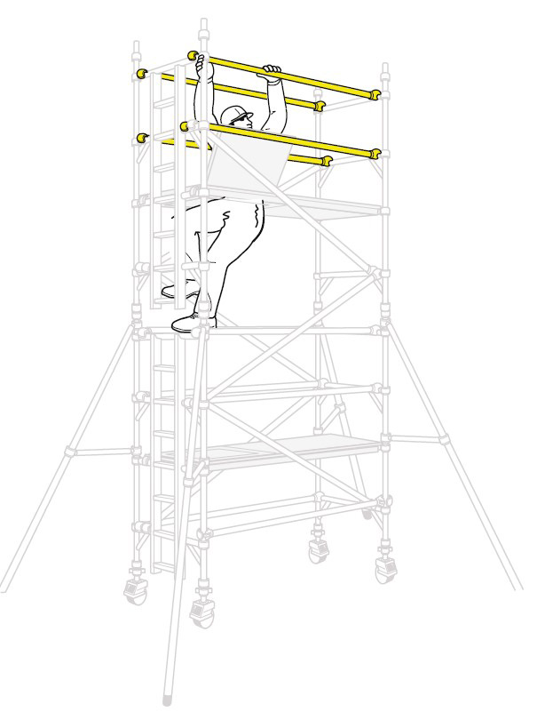
Fit a temporary deck on the lowest rungs. Fit a trapdoor deck on the 4th rung (2.0m) on one side of the tower. Ensure that the trapdoor is positioned with the hinges towards the outside of the tower as shown. Climb the end frame below the trapdoor on the inside of the tower, and from within the protected trapdoor position, fit guardrails on the 5th and 6th rungs (in that order) on both sides of the platform. Do not climb onto the deck until it is fully guardrailed. When horizontal braces are fitted as guardrails, they should be 0.5m and 1.0m (1 and 2 rungs) above the platform level in all cases. Remove the temporary deck from the lowest rung.
Fit Stabilisers
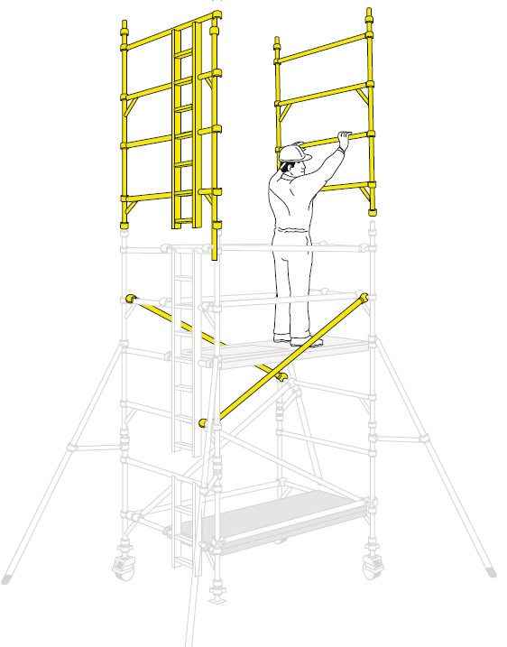
6:
Fit the next pair of diagonal braces in opposing directions between the 6th and 10th rungs add 2 additional end frames.
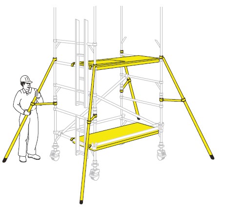
7:
Add two more diagonal braces between the 5th and 7th rungs. If finishing at this height (4.2m platform), reposition the fixed deck to the 8th rung on the tower. Fit a trapdoor deck alongside it with the hinges towards the outside of the tower and the trapdoor next to the ladder. Add a single diagonal between the 7th and 9th rungs as shown. Climb up the ladder, and from the protected trapdoor position, fit the guardrails on the 9th and 10th rungs, in that order, on both sides of the tower.
Assembly Procedure When Building Beyond a 4.2m Platform Height.
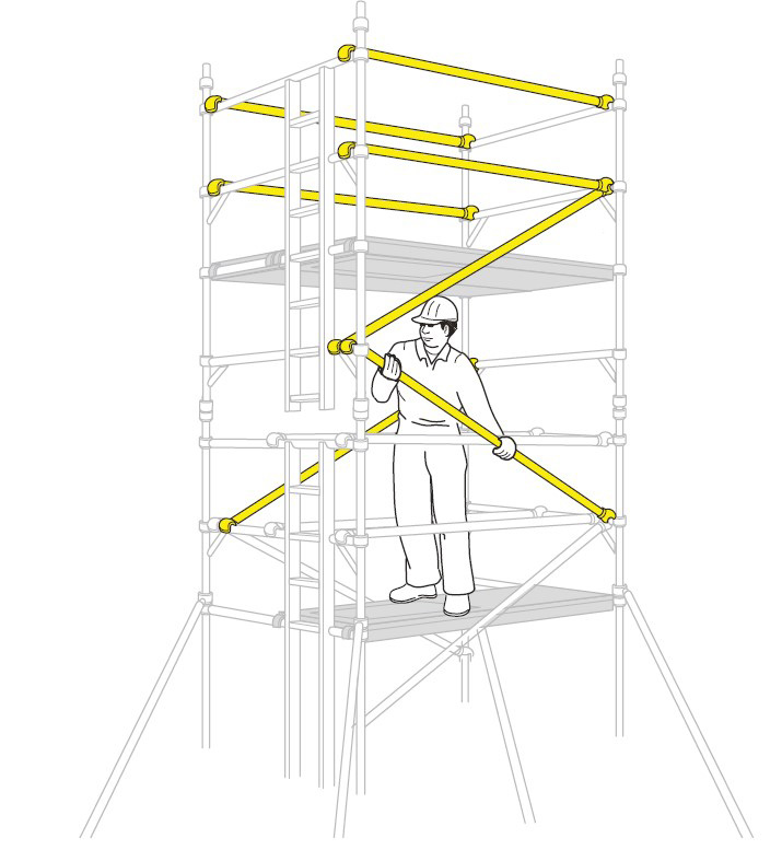
8:
Continue to add pairs of end frames, diagonal braces and fit trapdoor decks as shown in the previous steps. Add guardrails at 0.5m and 1.0m, (in that order), above the platform from the protected trapdoor position. Do not climb onto the platform until it is fully guardrailed. Continue until the required height is reached. Re-position the fixed deck to the required platform height and fit a trapdoor deck alongside it as shown in Stage 7. Fir a single diagonal at the top of the tower as shown in Stage 7. Fit the guardrails as shown in Stage 7.
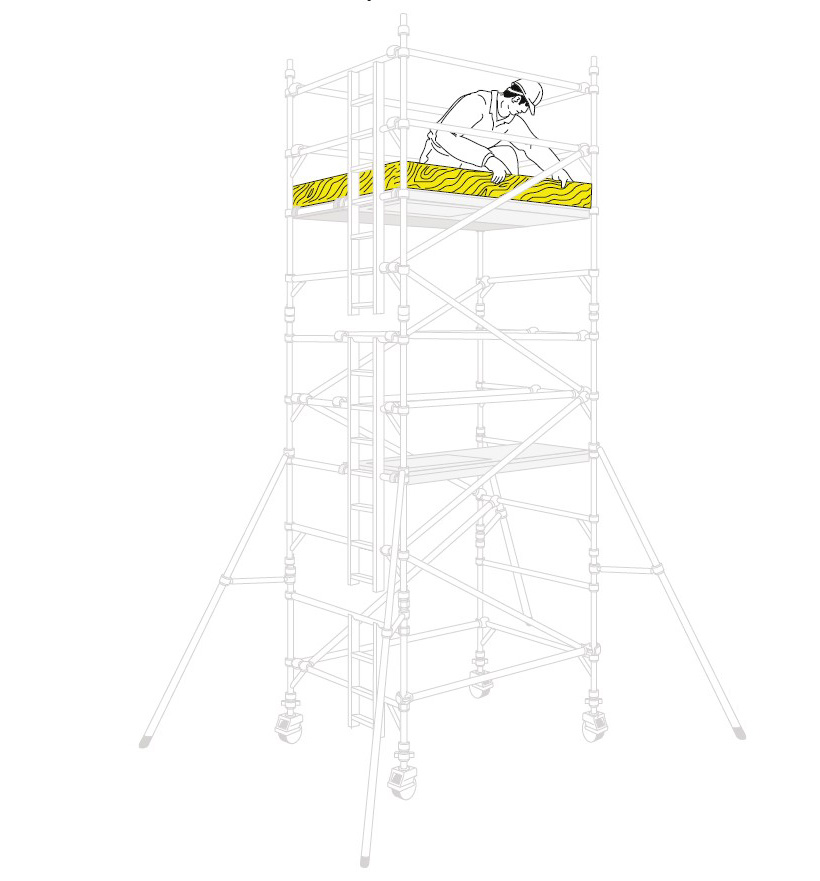
9:
Fit toeboards. The tower is now complete.
Dismantling Procedure for 1450 Towers
1:
To take down the tower, reverse the building sequence. When removing guardrail braces, unlock the claws furthest from the trapdoor and then return immediately to the protected position within the trapdoor. You may then unlock the claws at the other ends of the Guardrails to remove them from the tower.
Assembly for 850 Towers
Always start building with the smallest height frames at the base of the tower:
Where all 3 Heights are used in a tower, start with 2 rung frames at the base, with the 3 rung frames next and the 4 rung frames on top. Refer to the quantity schedules for detail. The procedure illustrated shows a 3.2m platform height tower starting with a 4 rung frame.
1:
Insert adjustable leg/castor assemblies into end frames and lock the castors, (see diagram Step 1). Base plates can be fitted to the adjustable legs if it is not necessary to move the tower. Fit 2 horizontal braces to the 850 end frames as shown in Steps 2 and 3 for the 1450 tower procedure.
2:
Fit a trapdoor deck on the 2nd rung. Fix the horizontal braces (red) as guardrails on the 3rd and 4th rungs (2 and 4 rungs above the platform) on both sides of the tower.
3:
Fit 2 diagonal braces (blue) in opposing directions between the 1st and 2nd rungs. Ensure the frames are vertical and level by checking with a spirit level and setting the adjustable legs as necessary. Fit stabilisers (see notes on page 30). Fit the next pair of end frames and check the frame interlock clips are engaged. Important: Only use the adjustment on the legs to level the tower and not to gain extra height.
4:
Fit 2 pairs of diagonal braces in opposing directions between the 3rd and 5th rungs and the 5th and 7th rungs. Locate a trapdoor deck on the 6th rung, with the trapdoor next to the ladder.
5:
Climb up the inside of the tower and from the protected position of the trapdoor, fit guardrails to the 7th and 8th rungs (in that order) on both sides of the tower.
6:
Continue the procedure until the required working height is reached, adding additional pairs of end frames, diagonal braces and fitting trapdoor platforms, as shown on previous steps. At every platform level, add horizontal braces as guardrails from the protected position within the trapdoor (as shown in Step 5). Fit a single diagonal at the top of the tower as shown. Fit the toeboards. The tower is now complete.
Dismantling Procedure
To take down the tower, reverse the building sequence. When removing guardrail braces, unlock the 4 claws furthest from the trapdoor and return immediately to the protected position within the trapdoor and then return immediately to the protected position within the trapdoor. You may then unlock the claws at the other ends of the guardrails to remove them from the tower.
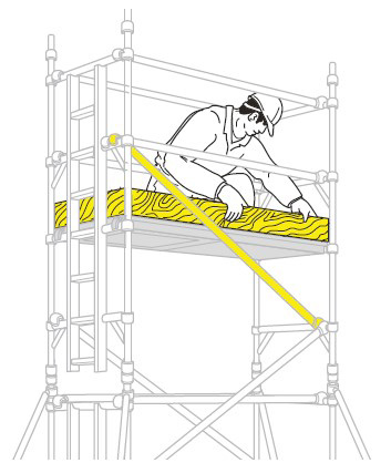
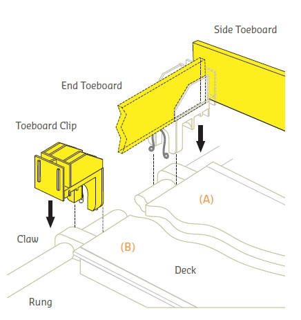
Fitting Toeboards
To take down the tower, reverse the building sequence. When removing guardrail braces, unlock the 4 claws furthest from the trapdoor and return immediately to the protected position within the trapdoor and then return immediately to the protected position within the trapdoor. You may then unlock the claws at the other ends of the guardrails to remove them from the tower.
Stabilisers
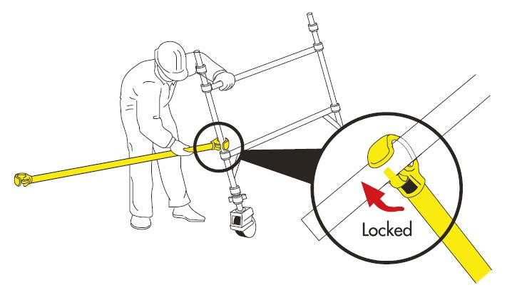
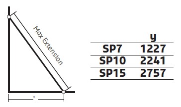
Attach one stabiliser to each corner of the tower as shown. Ensure stabiliser feet are equally spaced to form a square. SP10 and SP15 telescopic stabilisers must always be fully extended.
Position the lower clamp so that the lower arm is as close to the horizontal as possible. Adjust the position of the top clamp to ensure the stabiliser foot is in firm contact with the ground. Ensure clamps are secure.
Stabilisers are used when the tower is to be moved occasionally, frequent movement will require mobile outriggers.
When moving the tower, adjust the top clamps to lift the four stabiliser feet a maximum of 25mm off the ground and then unlock the castor brakes. After moving, ensure all four stabiliser feet are repositioned in firm contact with the ground.
Stabiliser Dimensions
Outriggers
For information on mobile outriggers please consult your supplier.
Branches
4 Westerton Road,
East Mains Industrial Estate, Broxburn,
West Lothian, EH52 5AU
T: 01506 863 864 F: 01506 863 916
Unit H, Hangman’s Wood Ind Park,
Stifford Road, South Ockendon,
Essex, RM15 6RL
T: 020 7473 6056 F: 01708 858 493
Forward House, Portobello Road
Portobello Industrial Estate, Birtley,
Tyne and Wear, DH3 2SN
T: 0191 492 1190 F: 0191 411 1148
Unit 4 Vauxhall Industrial Estate,
Greg Street, Reddish,
Stockport, SK5 7BR
T: 0161 477 0131 F: 0161 477 7618
Unit 20B Greens Industrial Park,
Calder Vale Road, Wakefield, WF1 5PH
Trinity Street, Off Tat Bank Road
Oldbury, West Midlands, B69 4LA